Do not select on anything in the drawing area. From properties un-check the Rotate with component.

About Drawing Pipe In A Section View Revit 2021 Autodesk Knowledge Network
Open the tag family.

. Set the offset select your whole piping run with tab click to place pipe and it makes the bends too. Then it sets a yesno Is Vertical parameter which you can use for view filters or schedules. You may need to move it in the 3D view to the correct location once the downpipe is modelled.
Creating some basic families specific for the company to use. In the Parameter Properties dialog box choose Pipes from the selection list at right as well as Pipe accessories and fittings if. Im an MEP guy with several years of Revit experience.
Navigate to a suitable elevation view and draw your Gutter Downpipe as required. Select Sketch Path on the Sweep Panel. In the drawing area click to establish a start point for the pipe.
Creating a starter project template for Revit. Click Systems tab Plumbing Piping panel Pipe or Pipe Placeholder. After you create the first segment shown by the arrow below change the pipe size to 100 mm.
1 Start piping command while in plan and pick a offset point say 0-0 at current floor level. Then copy the whole group of parallel pipes rotate change height if needed trim everything. Keep in mind the down spout insertion point is in the center of the pipe and that is the point that will align with our path.
In Ortho mode cursor movement is constrained to the horizontal or vertical direction relative to the UCS. Or Offset works for a single parallel pipe. Posted by Cherisse Biddulph on 10032014 at 1124 AM in Autodesk Revit Building Solutions Permalink.
If prompted to choose a work plan select the work plane previously defined Drain Pipe. Its a dynamo script that gets the end coordinates of all pipes and checks if they have the same X and Y coordinates Therefore the pipe is vertical. Beam now modelled in Revit with Curve rising in the vertical Z Axis.
Select the Pick Lines draw tool and highlight one edge of the curve at the end of the Revolved Generic Model. Optionally in the Properties palette under Mechanical select a system type. There is no built in way to filter vertical stuff but you can try this.
Is there an ortho in Revit. In the example below only the drain pipes are shown as 2-lines. A vertical segment is automatically created extending from the original offset to the newly applied offset.
Of particular interest are two items the Diameter textboxes B and the Offset combo box C. On the Options Bar specify a different Offset click Apply and click Modify. On the Place Pipe tab Placement Tools panel select placement options.
This will allow us to draw the path we want the down spout profile to travel. In Manage Project parameters create a shared project parameter called Unit Number or as desired. Load the family into your project.
Make sure it is an instance parameter. To Draw a line of Pipe using the selected system click on the button for Straight Pipe in the SysQueSystems Pipe system window. Connect to the right most water closet connector and draw a pipe with 135 deg to the left.
Consider a plan view that shows a vertical pipe with one of its ends being at the floor youre viewing If I want to continue the pipe run I find it difficult to get the pipe command to snap to the correct end It often snaps to the end not visible in the current view - which is just annoying Im also not having much luck using TAB to switch between the two ends. When you set the view Detail Level to Fine Revit shows all pipes as 2-lines. Basic training for people who dont know Revit software.
And yes that slope is 227739 1932 12 technically mathematically impossible but there it is. Across the top of the modeling area appears a new properties bar. Click once to enter a start point for moving.
2 I then enter the vertical offset height of this pipe say 8-0 at current level. I also avoid sloping pipe unless Im specifically required to do it which I almost never am The reasons. Showing 1-line drawing for small pipes and 2-lines for larger pipes in a common practice in MEP drawings.
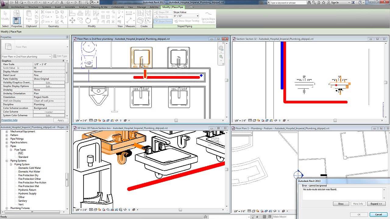
Troubleshoot and assistance on Revit for anyone using it. Then specify the following tagging options. Attached is a screen shot of a typical situation where as a result of pipe constantly moving within Revit a vertical pipe has developed a slope.
In Revit there is no setting to have a view like above. I pick the point where to start pipe. In the Type Selector select the pipe type.
Creating an outline for a BIM Execution Plan. The chamfered tees and elbows appear as 90 angles when sloped. Move the cursor in the direction that you want the element to move.
Revit license purchases and installs for 5 - 10 users. To Create Gutter Down Pipes in Revit go to the Systems Tab Pipe. Slope in Vertical Pipe.
Just draw all the pipes in one short section with the correct spacing. Make sure the pipe size is 50 mm and the offset is -1000. Want to know how to draw orthogonally in Revit commonly referred to as Ortho F8 in AutoCAD.
Click again to complete the move or for more precision type a value for the distance to move the element and press Enter. On the Options Bar click the desired options. While in a draw command like Wall Pipe or Grid Line hold down the SHIFT key.
You should now have the beam modelled across all 3 axis. Change the properties of the pipe to suit your needs. However from the Floor Plan view you can pick a start point and elevation for a pipe run via the OFFSET option example 9 then change the OFFSET value to something much higher 30 and select the.
On the Place Pipe tab Placement Tools panel select placement options. Now type BM to access your beam modelling command in Revit. Now connect all the water closet with the drain pipe you created.
Then connect to the main pipe. We draw our plumbing in single-line coarse view mode but this doesnt work well with sloped piping. You will have to do this for duct tags and pipe tags.
On the ribbon verify that Tag on Placement is selected to automatically tag pipes. As Julian said section views are the best to draw vertically but you do need a specific something there to start with end of a pipe connector on fixture etc.

Revit Mep Pipe Elevations Youtube
How To Place A Vertical Pipe In Revit Tutocad

Show Only Vertical Pipe Ducts And Cable Tray On Floor Plan Autodesk Community

Revit Mep Vertical Offset Youtube
Modelling Revit Pipes At A Vertical 45 Degree Angle Imaginit Building Solutions Blog
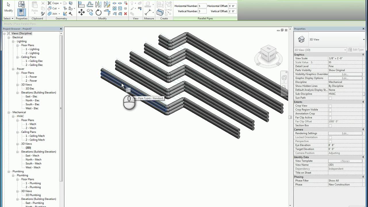
Revit Parallel Pipes Conduits Youtube
About Drawing Pipe In A Section View Revit Autodesk Knowledge Network

Vertical Pipe 45 Degrees Youtube
0 comments
Post a Comment